Building the FR Gunderson Husky-Stack Car
 In the first part of 2001, Freudenreich Feinwerktechnik (FR) released the Gunderson Husky-Stack container car, the first commercially-available Z-scale modern-era American freight car.
It's 68 scale feet long, with a 48 scale foot-long well, designed to accommodate Marklin containers - it's a great match for the American Z Lines C44-9W.
Made from photo-etched nickel-silver, this beautiful model is both strong and delicate.
It's available fully built and detailed by Harald himself, or in kit form.
In the first part of 2001, Freudenreich Feinwerktechnik (FR) released the Gunderson Husky-Stack container car, the first commercially-available Z-scale modern-era American freight car.
It's 68 scale feet long, with a 48 scale foot-long well, designed to accommodate Marklin containers - it's a great match for the American Z Lines C44-9W.
Made from photo-etched nickel-silver, this beautiful model is both strong and delicate.
It's available fully built and detailed by Harald himself, or in kit form.
The following instructions are from my experience building my FR Gunderson Husky-Stack kits.
In this article:
See also:
Feel free to write me if you have any additions or corrections to this page. Click on any photo to see more detail.
Before You Begin
Here are a few general getting-started tips for building photo-etched nickel-silver, stainless-steel, and brass kits:
Assembly
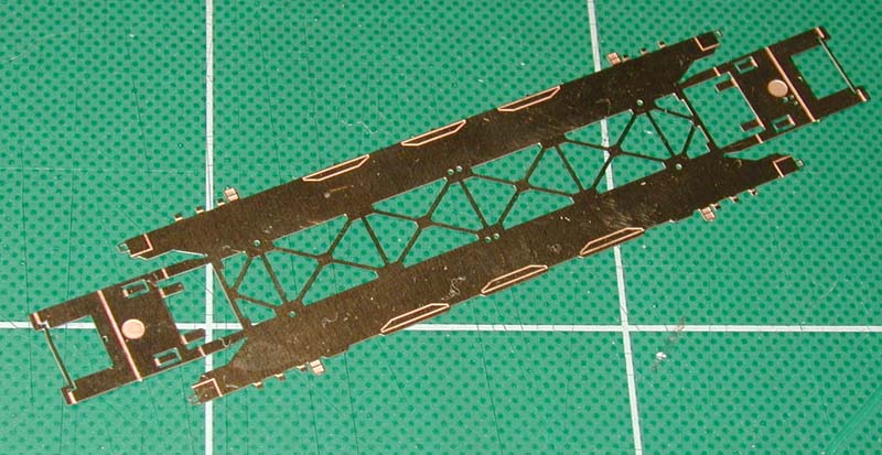 Remove the main frame from the parts sheet, and trim the burrs as described above.
The end pieces are very fragile - try not to bend them at all until step 5.
Remove the main frame from the parts sheet, and trim the burrs as described above.
The end pieces are very fragile - try not to bend them at all until step 5.
 The sides of the car are the first to be folded.
The difficulty here is that the center bracing is weaker than the fold lines - if you're not careful, you'll mangle the center bracing while trying to fold up the sides.
The sides of the car are the first to be folded.
The difficulty here is that the center bracing is weaker than the fold lines - if you're not careful, you'll mangle the center bracing while trying to fold up the sides.
Fortunately, I've come up with an easy and safe way to do it!
Obtain a length of 0.10" x 0.10" L-shaped brass channel from your local hobby shop, and glue it to a scrap piece of wood (hot-melt glue works very well here).
|
Folding Tool Tip 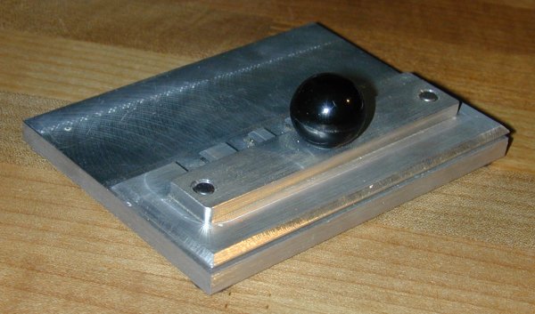 The Small Shop sells "The Hold and Fold Photoetched Parts Workstation," a tool used to aid in the bending of photo-etched kits like this one.
Since this article was written, I have purchased and used one of their "Hold and Fold" tools, and have found it to be absolutely indespensible.
If you build more than one photo-etched kit, this tool is a must-have!
The Small Shop sells "The Hold and Fold Photoetched Parts Workstation," a tool used to aid in the bending of photo-etched kits like this one.
Since this article was written, I have purchased and used one of their "Hold and Fold" tools, and have found it to be absolutely indespensible.
If you build more than one photo-etched kit, this tool is a must-have!
|
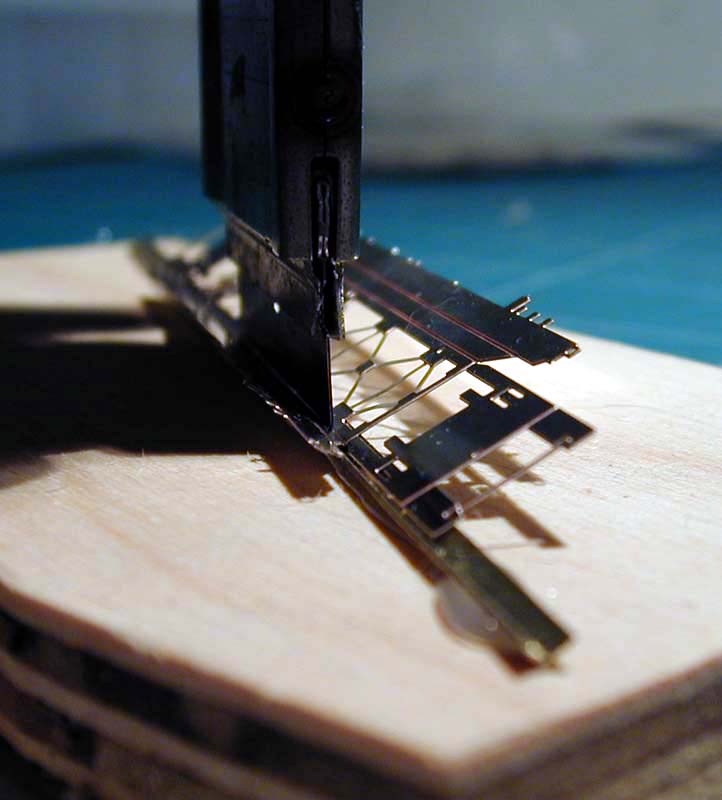 Next, place the piece on top of the brass channel with the fold line facing up and aligned parallel to the channel.
Place a razor-blade scraper in the fold line, and press down.
The harder you press, the more the piece will be bent - all without stressing the other joints.
You'll most likely have to apply pressure all across the joint to get an even fold (eyeball it as you go).
Next, place the piece on top of the brass channel with the fold line facing up and aligned parallel to the channel.
Place a razor-blade scraper in the fold line, and press down.
The harder you press, the more the piece will be bent - all without stressing the other joints.
You'll most likely have to apply pressure all across the joint to get an even fold (eyeball it as you go).
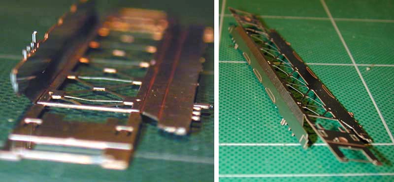 First fold the inner joint roughly 75o from horizontal.
Then, fold the joint closest to the edge an additional 15o or so, as shown in the photo.
First fold the inner joint roughly 75o from horizontal.
Then, fold the joint closest to the edge an additional 15o or so, as shown in the photo.
Repeat for the opposite side. The etched details (shaped like three trapezoids) should end up on the outside of the car.
 Now it's time to bend the ends.
Start with the folds closest to the center and make your way outwards.
Do this slowly and carefully the first time to avoid any mistakes.
Now it's time to bend the ends.
Start with the folds closest to the center and make your way outwards.
Do this slowly and carefully the first time to avoid any mistakes.
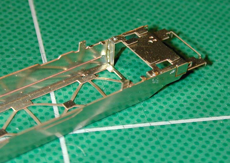
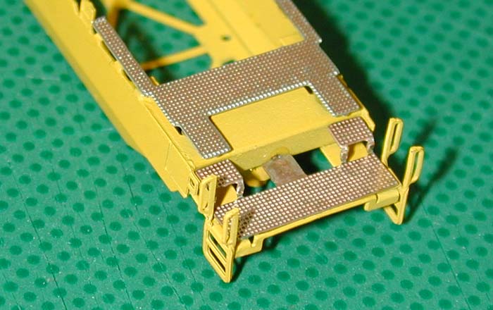
Bend the first fold 90o upwards, so that the angled contours are flush against the sides of the car. Bend the second and third folds downwards, both 90o, so that they follow the sides of the car. Bend The fourth fold 90o upwards, and the fifth and final fold 90o downwards.
The photo shows the end of the car folded correctly (see step 7 for details on the tabs).
Before soldering, however, eyeball the chassis from each end, making sure it's straight and true - if it is tweaked, take this opportunity to gently twist the chassis until it has been straightened out.
 Flip the model over, and carefully solder the joints as shown in the photo.
If there is any gap here, return to step 4 and correct the folds.
Flip the model over, and carefully solder the joints as shown in the photo.
If there is any gap here, return to step 4 and correct the folds.
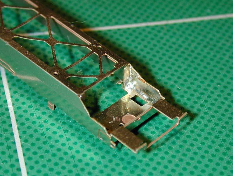
I've found it easiest to hold the tip of the soldering iron against the outside of the car, while melting the solder on the inside. Soldering is done on the bottom for aesthetic as well as structural reasons.
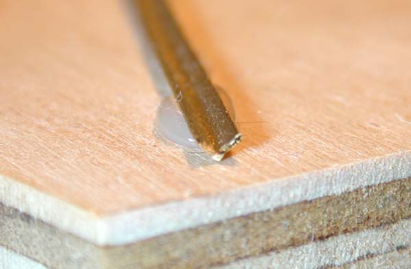
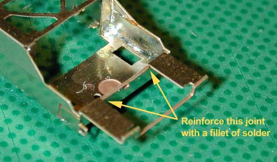
Lastly, reinforce the lower deck joint with a fillet of solder (see this closeup for details), which should help prevent breakage due to fatigue.
The lower treads, glued in step 12, will not only cover up any solder you put here, but will provide further reinforcement as well.
Now is a good time to make sure once more that the chassis is straight - if it isn't, twist the chassis until the front and rear decks are perfectly aligned. If the chassis is at all tweaked, it won't sit evenly on the tracks, and will derail if you do so much as look at it cross-eyed.
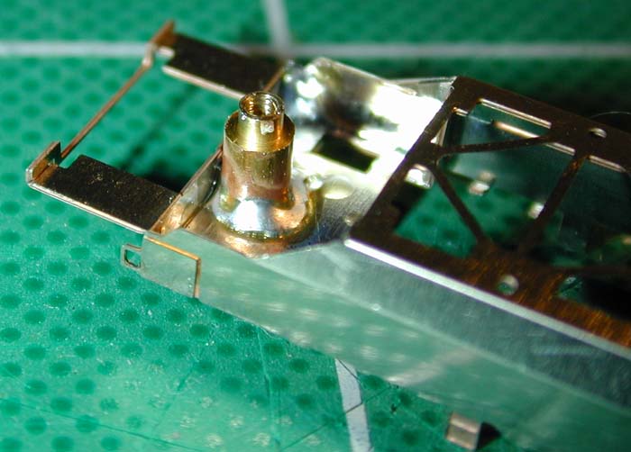 Each chassis comes with two bolster pins that hold the trucks.
With the chassis upside down, place the two bolster pins into the circular indentations, and solder them into place.
I found it easiest to hold the pins down against the chassis with the soldering iron tip, and applying solder around the base of the pin.
You may want to use a heat sink (a hunk of metal, such as alligator clips or a lead weight, to absorb and dissipate the heat) so that the existing solder joints aren't disturbed.
Each chassis comes with two bolster pins that hold the trucks.
With the chassis upside down, place the two bolster pins into the circular indentations, and solder them into place.
I found it easiest to hold the pins down against the chassis with the soldering iron tip, and applying solder around the base of the pin.
You may want to use a heat sink (a hunk of metal, such as alligator clips or a lead weight, to absorb and dissipate the heat) so that the existing solder joints aren't disturbed.
Note that each pin should be centered in the indentation, and should be perpendicular to the deck.
(The the bolster pin in the photo looks off-center, but it's only an illusion.)
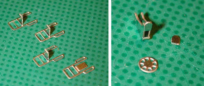 The next step is to prepare the details: four ladders, one brake wheel, and one brake wheel stand.
You'll find one extra ladder and brake wheel in case you screw up.
The next step is to prepare the details: four ladders, one brake wheel, and one brake wheel stand.
You'll find one extra ladder and brake wheel in case you screw up.
Bend the ladders and brake wheel stand as shown in the photo. Next, twist the hand rails on the ladders so that they point outwards when mounted on the chassis. Be very careful not to bend or twist any of the pieces too much; at the same time, make sure the hand rails are all as close to vertical as you can make them.
Here, the tiny piece shown next to the brake wheel stand was accidentally broken off when I tried to bend it down.
Whether or not you break it, though, it must be glued in place between the stand and the wheel (as described in the next step).
Harald recommends reinforcing the tongue with a tiny bit of solder before bending, and then re-melting the solder (with a soldering iron or butane torch) to permanently fix the tongue to the stand.
This works very well!
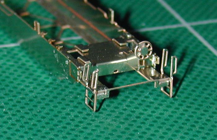 Insert the brake wheel stand into the two holes on one side of the chassis, and then insert the brake air reservoir into the larger adjacent hole (you may have to enlarge it slightly with an X-acto knife).
The details can then be soldered or glued into place from underneath.
Insert the brake wheel stand into the two holes on one side of the chassis, and then insert the brake air reservoir into the larger adjacent hole (you may have to enlarge it slightly with an X-acto knife).
The details can then be soldered or glued into place from underneath.
Next, place the ladders on the outer corners, with the hand rails pointing upwards, putting a tiny bead of CA glue under each of the tabs. Lastly, glue the brake wheel to the stand; the photo shows all the details in place, except for the brake air reservoir.
All that's left are the treads, but since they don't get painted, they'll have to wait.
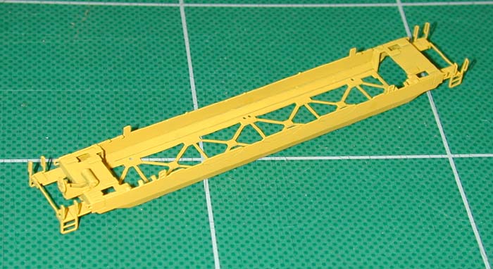 Paint the entire chassis at this point, as described above.
To support the model during painting, I inserted two brass wires into the bolster pins and attached them to a stable base.
Paint the entire chassis at this point, as described above.
To support the model during painting, I inserted two brass wires into the bolster pins and attached them to a stable base.
If you're decorating your cars in the classic TTX livery (see below), use Floquil "Reefer Yellow" (#110031).
As for the other schemes, I can obtain the proper paint colors if anyone asks.
 Once the paint has dried, it's time to glue the treads into place.
Be careful not to let the glue damage any of the paint; less is more.
If you use odorless Super-Gold+ CA glue, you won't have to worry about the fogging that can occur.
There are four treads, two upper "H"-shaped treads and two lower "W"-shaped treads.
Once the paint has dried, it's time to glue the treads into place.
Be careful not to let the glue damage any of the paint; less is more.
If you use odorless Super-Gold+ CA glue, you won't have to worry about the fogging that can occur.
There are four treads, two upper "H"-shaped treads and two lower "W"-shaped treads.
Lower treads: Gently bend up the two steps on each of the lower treads, as shown in the photo. Test fit the piece before gluing, and adjust the steps as needed. Note the tiny tab on the tread and the hole in the chassis to which it mates; you may have to trim the tab if the hole is blocked by the bolster pin. Place a tiny dab of glue on each point of contact, including the edges of the steps, and glue the tread into place.
Upper treads:
The ten little tabs bent in step 7 are the only contact points for the upper treads, so make sure they're fairly uniform at this point.
Test fit the piece before gluing; you may have to trim the long tips to get the tread to rest square on the deck.
Put a tiny dab of glue on each tab, and attach the tread.
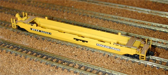 The last step is to apply the decals.
Included with each kit are six water-slip decals, three per side.
The decals for the TTX design are placed so that their baselines are just above the upper fold line, as shown in the photo.
If you're decorating your husky stack cars with a different road name, see Prototype Information, below.
The last step is to apply the decals.
Included with each kit are six water-slip decals, three per side.
The decals for the TTX design are placed so that their baselines are just above the upper fold line, as shown in the photo.
If you're decorating your husky stack cars with a different road name, see Prototype Information, below.
Use an X-acto knife to cut out each decal, removing as much of the border as you comfortably can. Then, submerge the decal in room-temperature water for a minute or so, until the decal comes loose from the paper backing. Use a pair of tweezers to carefully apply the decal to the chassis, and then soak up the excess water with a piece of toilet paper. If the decal dries before it is positioned correctly, a little bit of water can be used to loosen it.
To protect the decals, I recommend brushing a tiny amount of Microscale Liquid Decal Film over them (just past the edges of the decals).
Once the film dries, you shouldn't be able to notice it.
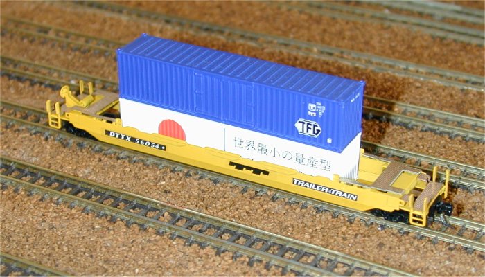
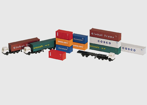
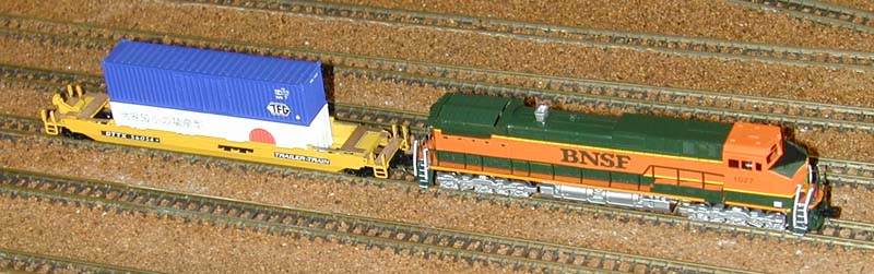 Now, here's the best part - these husky stack cars are specifically designed to accommodate Marklin containers, either those that come with other Marklin flat cars (such as the ones I've used in this picture), or as part of the Marklin 89010 kit.
The prototype typically has two containers, and luckily, the Marklin units have tiny pins and holes that allow stable stacking - there are even holes for the pins in the FR Husky-Stack cars to accommodate half-length and full-length containers.
This one is ready to roll!
Now, here's the best part - these husky stack cars are specifically designed to accommodate Marklin containers, either those that come with other Marklin flat cars (such as the ones I've used in this picture), or as part of the Marklin 89010 kit.
The prototype typically has two containers, and luckily, the Marklin units have tiny pins and holes that allow stable stacking - there are even holes for the pins in the FR Husky-Stack cars to accommodate half-length and full-length containers.
This one is ready to roll!
Prototype Information
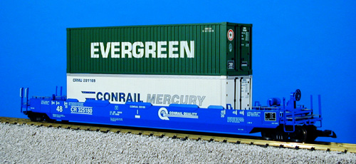
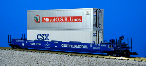
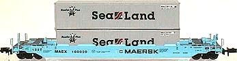
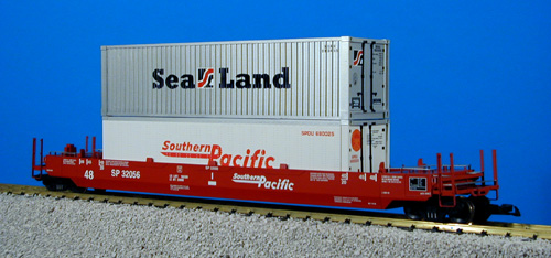
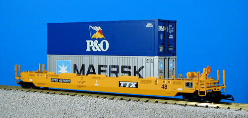
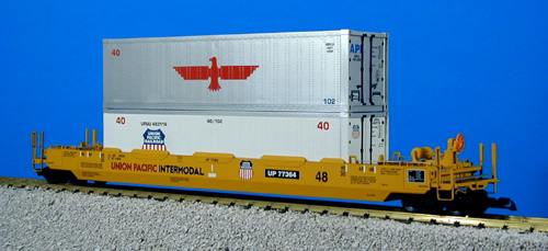
The Husky-Stack container cars, made by Gunderson, Inc., are available as either stand alone single units (with a set of wheels and coupler on each end) or as three unit sets with solid draw bars and shared wheelsets between the center and end units to accommodate unusually heavy double stack container loads. The additional wheelsets on the Husky Stack cars afford additional capacity and braking ability, allowing heavier loads than with conventional, articulated double stack cars. With it's low center of gravity, it can handle a single 48-foot container, or two stacked containers.
Right now, information on these cars is scarce. There's no specific details on the Gunderson, Inc., site, and finding photos has been difficult. However, the Intermodal Modeler’s Guide, both Volume 1 and Volume 2, has lots of detailing info on the Husky-Stack cars.
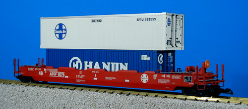
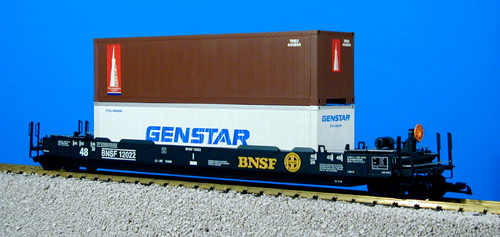
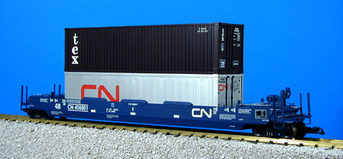
I've been able to find a few photos of the different paint schemes in which the Husky-Stack has been seen:
I'll post more details on colors when the information becomes available. (Thanks to USA Trains for the photos.) Comments are welcome!
Return Home | Search | Contact Me
Copyright © 2000-2010 D. A. Karp. All rights reserved.