Multi-Unit Locomotive Wiring
Model railroads, like the prototypes, often employ trains powered by multiple locomotives. Not surprisingly, two locomotives have twice the pulling power and twice the traction of one.
In this article:
See also:
Feel free to write me if you have any additions or corrections to this page. Click on any photo to see more detail.
Improving Marklin Multi-Unit Wiring
Marklin wires together the engines in their multi-locomotive sets in one of two ways:
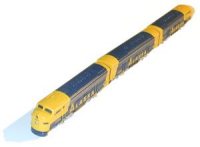 Two GM EMD F7-A units are directly wired together and coupled permanently to each other.
Examples are the 8819 Alaska A-B-A set (see photo) and the 8832 Union Pacific A-B-A set.
Two GM EMD F7-A units are directly wired together and coupled permanently to each other.
Examples are the 8819 Alaska A-B-A set (see photo) and the 8832 Union Pacific A-B-A set.
Regardless of the configuration, the idea is to have two locomotives wired in parallel so that one is never running while ther other is not. Marklin also includes diodes (which allow current to run only in one direction) in the circuitry such that the power pickup is only made by the forward unit. This makes block operations (where two or more sections of track are isolated from one-another) easier and safer, preventing derailing and short-circuits.
Unfortunately, the diodes cause two problems. First of all, a single diode causes a voltage drop of 0.6 volts. Marklin uses four diodes in each pair of F7 units, two per powered unit. There are eight diodes in the 8871 ICE and 8873 TEE, two for the motor, and two for the directional lighting in each unit. That's a voltage drop of 1.2 volts for the motors; at full throttle, that means only 6.8 volts (85% of maximum) is actually powering the locomotives. Secondly, it means that at any given time, two locomotives are only getting the benefit of the power pickup of one unit. A little bit of dirt on the track will stop a multi-locomotive train as easily as it will stop a single unit.
The Marklin 8871 ICE and 8873 TEE sets suffer from an additional problem. Since cars and couplers carry the current between the powered units, the connection (and therefore the performance of the train) can be sporadic, especially around tight curves. Additional intermediate cars can also add resistance to the whole system, further reducing performance (see Improving Locomotive Power Pickup for additional ICE tips). If you detach one of the powered units from the train, you'll notice it only goes forward; change the direction on your transformer, and it won't move at all. This is, of course, what happens when the connections between the two powered units fail - the whole train stops.
The solution is to eliminate the diodes, which will improve performance and allow both units to pickup power simultaneously, essentially eliminating stalls and erratic running. After the following procedure, you'll find details on wiring two separate units to one-another.
You'll need a soldering iron, solder, and some fine-gauge wire.
If you're working on the Marklin 8819 or 8832, you'll need to be careful of the wires poking through the rear windows of the A units.
Also, be gentle with the permanent couplers on the F7 units; while they're relatively sturdy, the pins in the trucks that hold them break easily.
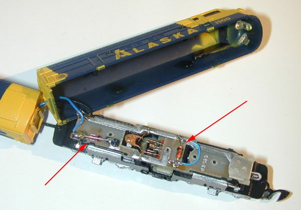 The red arrows in the first photo show the locations of the diodes in the 8819 Alaska F7 set (the 8832 Union Pacific is the same).
You don't need to remove the diodes; only bypass them with a short length of fine wire.
You'll notice that I've already done this to one of the diodes in the photo (see the blue wire); you'll want to do this for both diodes.
Since electricity follows the easiest path through a circuit, this effectively bypasses the diodes, and eliminates their drain on the power.
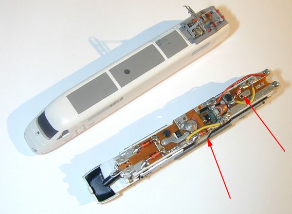 The red arrows in the second photo show the locations of the diodes in one of the powered units of the 8871 ICE set (the 8873 TEE set is similar).
You'll notice that two of the diodes in the photo already have pieces of yellow wire soldered to the diode leads. The other two diodes (located in the front of the locomotive) are for the directional lighting, and should not be bypassed.
Thanks to Graham Jones, ZClub(GB), for this diagram showing the diode locations on TEE and ICE units.
In my opinion, the best type of wire to use is phonograph needle wire (it connects the needle to the record player base - remember record players?); it's soft, flexible, and very thin. You should be able to find it at a neighborhood electronics store or vintage stereo repair shop. You can also use speaker winding wire, which is even thinner, albeit more fragile, than phonograph needle wire.
Start by cutting a 1/2" to 3/4"-long piece of wire, and stripping the ends. Using a soldering iron with a fine point, carefully -- and briefly -- melt the solder at one end of the diode, and put one end the wire in place with a pair of tweezers. Then, briefly melt the solder at the other end of the diode, and use the tweezers to connect the other end of the wire. You shouldn't need to add any more solder, but if you do, use a tiny bit of .040" diameter rosin 5-core solder.
Your work should look something like the photos, above.
For the 8871 ICE and 8873 TEE units, you'll notice now that the powered units run in both directions, even when they're not connected to the train.
Likewise, both units pick up power simultaneously, and are no longer susceptible to sporadic connections in the intermediate cars.
Should you ever wish to return the units to their former state, just cut or remove the bypass wires.
Making Your Own Wired Multi-Unit Locomotives
You already know the advantage of using two or more locomotives to pull the same train. And, as stated above, if they're wired together, they will share the current they pick up, and won't be nearly as susceptible to dirty track.
 Fortunately, you're not limited to the wired multi-unit sets that Marklin sells; you can make your own quite easily.
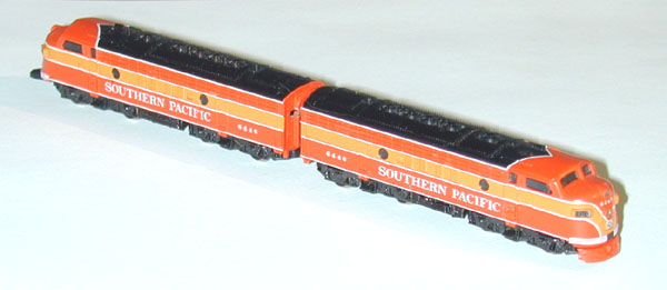
I wired together two Marklin 8809 Souther Pacific 'Daylight' F7 locomotives, back-to-back, like the prototypes. While different locomotives will present different problems as for wiring, you should be able to do it with any powered unit you're not afraid to take apart.
You'll need a soldering iron, solder, and some fine-gauge wire. It also will help to have an X-Acto knife, and a rotary tool (such as a Dremel) with a small cutting disk.
Note: although this procedure deals with Marklin units, Micro-Trains locomotives can also be wired together.
Details on wiring (and close-coupling) two Micro-trains F7 units can be found in the September/October 2001 issue of Ztrack Magazine (volume 7, Number 5), page 12.
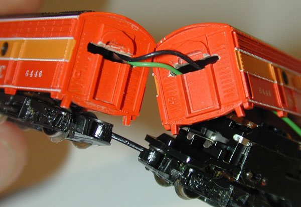 The wires between the F7 units pass through the rear window of each unit.
However, to accommodate sharp curves, you'll need to widen the windows by cutting a horizontal slot, as shown in the photo.
From my experience, all Marklin F7-B units already have the necessary slots.
The wires between the F7 units pass through the rear window of each unit.
However, to accommodate sharp curves, you'll need to widen the windows by cutting a horizontal slot, as shown in the photo.
From my experience, all Marklin F7-B units already have the necessary slots.
Using whatever tool you're comfortable with, such as a knife, a file, or a Dremel tool, make a slot as thick as the existing window (no thicker), and about 3/8" wide.
Make sure it's smooth, so the wires have nothing to catch on.
In my opinion, the best type of wire to use is phonograph needle wire (details earlier in this article). The two pieces of wire should also be of different colors, so you won't confuse the polarity.
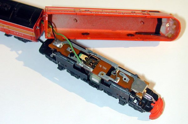 Solder one end of one of the wires to the small plate at the rear of the circuit board, as shown by the black wire in the photo.
Then, solder one end of the other wire to the other contact on the circuit board, as shown by the green wire in the photo.
Solder one end of one of the wires to the small plate at the rear of the circuit board, as shown by the black wire in the photo.
Then, solder one end of the other wire to the other contact on the circuit board, as shown by the green wire in the photo.
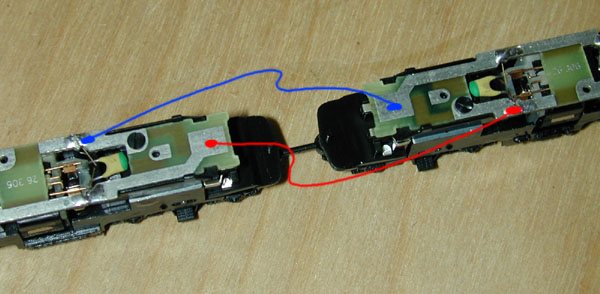 Now, solder the other ends of the two wires to the remaining locomotive, as shown by the red and blue lines in the photo.
Important: note the polarity; if the wires are reversed, neither locomotive will run.
If you get confused (which is likely), place both locomotives on a length of track (make sure the track power is turned off).
Use a continuity tester (a function on most multimeters) to verify which contacts on the locomotive circuit boards are correspond to the left rail, and which correspond to the right.
Now, solder the other ends of the two wires to the remaining locomotive, as shown by the red and blue lines in the photo.
Important: note the polarity; if the wires are reversed, neither locomotive will run.
If you get confused (which is likely), place both locomotives on a length of track (make sure the track power is turned off).
Use a continuity tester (a function on most multimeters) to verify which contacts on the locomotive circuit boards are correspond to the left rail, and which correspond to the right.
Once all the wires are soldered, carefully put the shells back on the locomotives.
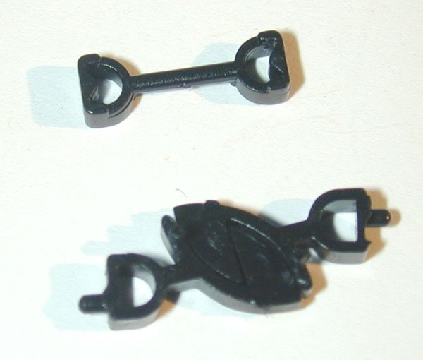 Next, you'll want to replace the standard couplers between the units with a single, permanent coupler.
Most Marklin F7 locomotives come with this part; if you don't have one, you can get them from a Marklin dealer (Marklin 436340, two in a package) for only a few dollars.
Next, you'll want to replace the standard couplers between the units with a single, permanent coupler.
Most Marklin F7 locomotives come with this part; if you don't have one, you can get them from a Marklin dealer (Marklin 436340, two in a package) for only a few dollars.
The permanent coupler, or drawbar, accomplishes several things. First, it brings the two units closer together, which looks better. Second, it is a permanent coupler which can't be uncoupled; you don't want to add any stress to the wire or your soldering job. Third, it eliminates the bounce between the units, making them behave more as a single locomotive. Last, it won't get caught in an automatic uncoupler.
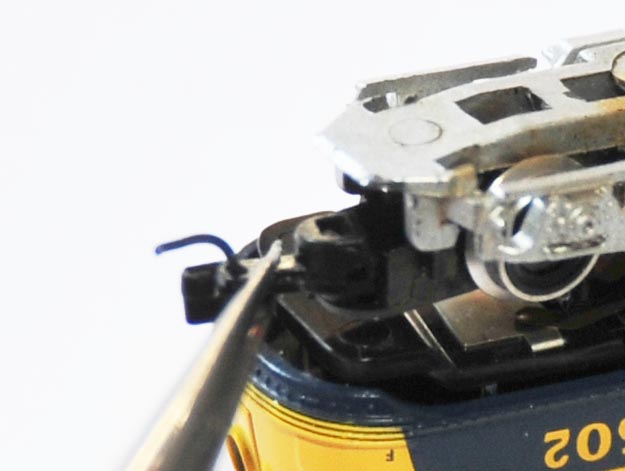
To remove the couplers from the F7 units, you'll need to bend down the plastic truck housing just enough to leave a 3/16" gap (as shown in this photo). Remove the old coupler (you can leave in the spring so it doesn't get lost) and insert the drawbar in its place. The notches on the end of the drawbar should face up (away from the rails), as shown here. Close up the truck when you're done. Different locomotives have slightly different truck designs, so you should refer to the included instruction sheet for details.
Use caution when performing this step, as the pins on Marklin's F7 trucks are quite fragile, and break easily.
Should you ever wish to return the units to their former state, just cut or remove the wires between the units, and reinstall the original couplers.
Return Home | Search | Contact Me
Copyright © 2000-2010 D. A. Karp. All rights reserved.