Improving Performance of the Rogue Locomotive Works GP38-2
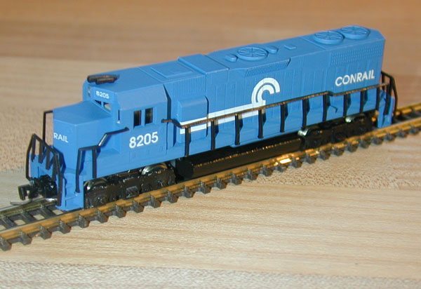 A few years ago, American Z Lines (formerly Rogue Locomotive Works) released the first-ever commercially available modern American diesel locomotive for Z-scale (of which I'm aware).
The Rogue GP38-2 is a terrific looking model, but it could benefit from some tweaks under the hood to help it run better.
What makes this especially difficult is that Rogue only made a few of these, which not only makes getting service or obtaining replacement parts essentially impossible, but increases the difficulty and intimidation associated with taking apart the expensive models.
A few years ago, American Z Lines (formerly Rogue Locomotive Works) released the first-ever commercially available modern American diesel locomotive for Z-scale (of which I'm aware).
The Rogue GP38-2 is a terrific looking model, but it could benefit from some tweaks under the hood to help it run better.
What makes this especially difficult is that Rogue only made a few of these, which not only makes getting service or obtaining replacement parts essentially impossible, but increases the difficulty and intimidation associated with taking apart the expensive models.
In working with my Rogue locomotives, I've come up with some tips to help them run better. While it's certainly the quietest locomotive I have, it does suffer from a few glitches in the gearing and design of the trucks. Rehabilitating these engines essentially involves disassembly, careful modification, and finally, reassembly.
|
A Word About Rogue It should be noted that designing a Z-scale locomotive from scratch for the purpose of mass production is an enormous undertaking. For a large company like Marklin, it reportedly takes a half-million dollars and over a hundred people to design a new model. Every part, except for the Faulhaber motor, the Grain-of-Sand lights, and the Micro-Trains couplers, was designed and produced from scratch by Rogue specifically for this model. See my review of the American Z Lines C44-9 for photos and information on their newest model, which is superior to the GP38-2 in just about every way.While the above article does discuss improvements to the Rogue engine, it should not be implied that I hold any view other than admiration for Rogue; they should be commended for attempting to expand the Z market with this model. See Reviving Marklin Locomotives for a similar article. |
You'll need a tiny slotted screwdriver like the ones that come with eyeglass-repair kits, a sharp pair of tweezers, and some lithium grease (found in the R/C section of most hobby shops). Also helpful is a multimeter with a continuity tester, and a rotary tool (Dremel, for example). Note that I make no guarantees or take responsibility for any unfavorable consequences resulting from these instructions. If your skills are not that honed, you're probably better off leaving this work to a more capable friend.
Feel free to write me if you have any additions or corrections to this page.
Click on any photo to see more detail.
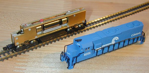 First, remove the shell from the chassis. This is a friction fit, so all you need to do is pull.
The best way is to grasp the overhang vents (above the 'C' logo in the photo) with one hand, while holding the fuel tanks with the other, and pull straight up.
Don't pry it apart with a screwdriver or try to pull on the trucks.
First, remove the shell from the chassis. This is a friction fit, so all you need to do is pull.
The best way is to grasp the overhang vents (above the 'C' logo in the photo) with one hand, while holding the fuel tanks with the other, and pull straight up.
Don't pry it apart with a screwdriver or try to pull on the trucks.
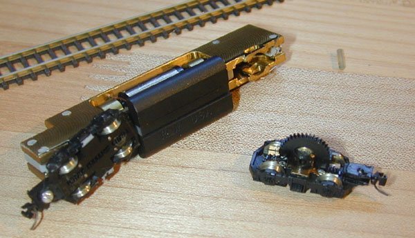 Next, remove the truck pin by pushing through with a small pair of tweezers or a small screwdriver.
Don't force it - if it sticks, try pushing from the other side.
Once it's off, put it somewhere safe, and the truck should come right off.
Next, remove the truck pin by pushing through with a small pair of tweezers or a small screwdriver.
Don't force it - if it sticks, try pushing from the other side.
Once it's off, put it somewhere safe, and the truck should come right off.
 The spur gears should just slide out at this point; they each consist of a plastic gear and a brass bushing.
The spur gears are a main source of the problem; we'll get to those later.
The spur gears should just slide out at this point; they each consist of a plastic gear and a brass bushing.
The spur gears are a main source of the problem; we'll get to those later.
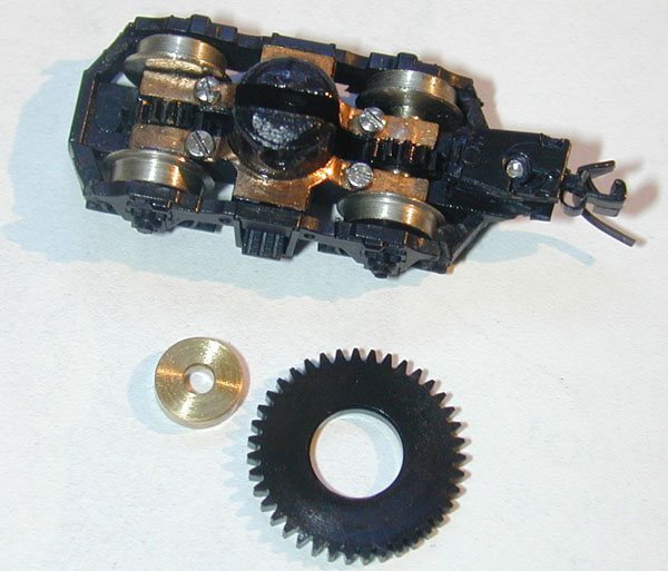
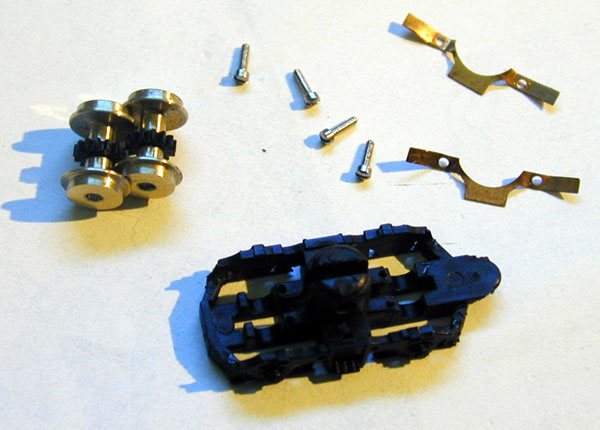 Completely disassemble the trucks.
This is accomplished by removing the four screws that hold the copper contacts, which in turn, hold the wheelsets in place.
You don't have to take off the couplers, unless you're worried that you'll break them.
Working on a white surface will help prevent loosing the pieces.
Completely disassemble the trucks.
This is accomplished by removing the four screws that hold the copper contacts, which in turn, hold the wheelsets in place.
You don't have to take off the couplers, unless you're worried that you'll break them.
Working on a white surface will help prevent loosing the pieces.
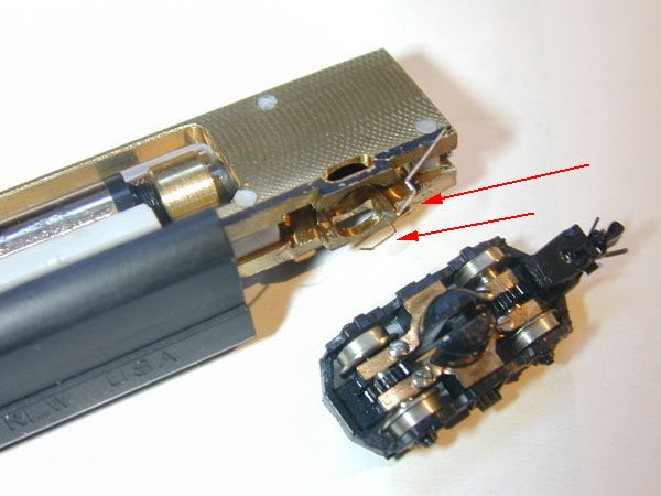
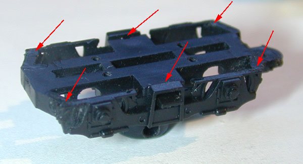 The first piece of surgery we'll perform is on the trucks themselves.
Turn the truck over so it is upside down (like the photo), and examine how it is glued together.
If it's glued unevenly, the locomotive will run erratically, it will get caught or derailed at turnouts, and it won't pick up power consistently.
The red arrows show the problem spots; the two in the middle are often the most severe (notice how the sides aren't flush with the bottom in this photo).
The first piece of surgery we'll perform is on the trucks themselves.
Turn the truck over so it is upside down (like the photo), and examine how it is glued together.
If it's glued unevenly, the locomotive will run erratically, it will get caught or derailed at turnouts, and it won't pick up power consistently.
The red arrows show the problem spots; the two in the middle are often the most severe (notice how the sides aren't flush with the bottom in this photo).
If you see any problems, You can use a knife or rotary tool to carefully remove any obtrusions.
Alternately, you can use a sharp knife to cut along the gluelines, and then carefully re-glue with a tiny amount of 6-minute epoxy (it's more work, but it means not compromising the appearance of the trucks).
With sharp tweezers, put the screws in the contacts, then place the copper contacts back on the trucks. (The raised centers of the contacts should face up.) The photo at step 3 shows a completed truck. Fasten the screws tightly, but don't strip the plastic.
Carefully bend the ends of the contacts with your sharp tweezers, so that they are firmly touching the wheels, but not so firm that they impede movement.
All four wheels should be touching the contacts.
It's important to note that when any weight is put on the trucks, it will push the wheels against the copper contacts (which is good).
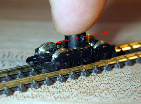 Place the truck on the track, and with a finger resting gently on the top, roll the truck back-and-forth repeatedly.
It should roll smoothly with only a little bit of resistance.
Too much resistance, and the locomotive won't move; not enough, and it's likely that electrical contact is not being made.
Next, using a continuity tester (a function on most multimeters), place one lead on a track rail, and another on one of the copper contacts on the truck.
If there is no current, bend those contacts down so that they're pressing against the wheels.
Repeat for the opposite rail and the opposite side of the truck.
Place the truck on the track, and with a finger resting gently on the top, roll the truck back-and-forth repeatedly.
It should roll smoothly with only a little bit of resistance.
Too much resistance, and the locomotive won't move; not enough, and it's likely that electrical contact is not being made.
Next, using a continuity tester (a function on most multimeters), place one lead on a track rail, and another on one of the copper contacts on the truck.
If there is no current, bend those contacts down so that they're pressing against the wheels.
Repeat for the opposite rail and the opposite side of the truck.
Now, there's not much you can do about the first two, other than replace the gears altogether. I'm actively seeking metal replacements, but I'm not holding my breath. If you've found a suitable replacement, or know where they can be acquired, please let me know!
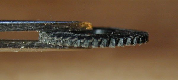 The profile, however, can be changed (not for the faint of heart).
If you look at the spur gears in Marklin locomotives (most diesels and electrics), you'll notice that they look like flying saucers; they're fat in the middle, and almost come to a point at the edge.
The Rogue gears are much thinner, so we don't have that much room to work.
However, you can take a rotary tool and gently grind the edges of the gears, as shown in the photo.
I used a fiberglass cutting disk (Dremel #426) at low speed, and used its top surface like a grinder.
Be careful not to remove too much material, and don't remove any material near the center.
If the gear is too thin, the teeth will break.
The profile, however, can be changed (not for the faint of heart).
If you look at the spur gears in Marklin locomotives (most diesels and electrics), you'll notice that they look like flying saucers; they're fat in the middle, and almost come to a point at the edge.
The Rogue gears are much thinner, so we don't have that much room to work.
However, you can take a rotary tool and gently grind the edges of the gears, as shown in the photo.
I used a fiberglass cutting disk (Dremel #426) at low speed, and used its top surface like a grinder.
Be careful not to remove too much material, and don't remove any material near the center.
If the gear is too thin, the teeth will break.
When you're done grinding, use a knife or synthetic steel wool to carefully remove the burrs.
Put a little lithium grease on the teeth, insert the brass bushing, and place the assembly into the truck.
Repeat step 7 (above) with the spur gear now in place.
The Faulhaber motor is mounted to the chassis with a plastic "cradle" that is glued to the motor and then positioned between the chassis halves with plastic pins. Sufficeit to say, this leaves a lot of room for error (as opposed to screws and metal mounting brackets, which would've been preferred). If the motor is not perfectly aligned, both vertically and horizontally, as well as longitudinally, the worm gears on the motor will not mesh smoothly with the spur gears. If the motor is loose at all, it will be much worse.
This is probably the most difficult problem to diagnose, as the plastic supports block the view of the worm/spur mesh. If the other solutions on this page don't result in a smooth running engine, you'll have to correctly align the motor. To do this, you'll have to loosen the motor from the mount (hopefully without having to disassemble the chassis). This is done by gently trying to slide it forwards and backwards until it starts to move; heating up the motor casing near the mount with a soldering iron (on a low heat setting) will help soften the glue.
Once the motor is loose, reposition it, keeping the following in mind:
When you think you've got a good fit, try reattaching the trucks (see the following step), and apply power by pressing a 9V battery against the top of the chassis, with each contact touching an opposite side.
Do the best you can to make adjustments with the power still applied.
When you're done, hold the motor in place and apply a little bit of 6-minute epoxy to the motor mount where it touches the motor, and wait for it to dry.
 Now you're ready to slide both trucks onto the chassis.
To reattach them, just slide the pin (removed in step 2) back in.
Don't force it!
If it doesn't go in smoothly, try adding a little lithium grease.
If the spur gear is even a little out of place, the pin won't go in.
Use your small screwdriver or tweezers to align the holes, and try again.
The pin should be flush with the brass chassis on both sides.
Now you're ready to slide both trucks onto the chassis.
To reattach them, just slide the pin (removed in step 2) back in.
Don't force it!
If it doesn't go in smoothly, try adding a little lithium grease.
If the spur gear is even a little out of place, the pin won't go in.
Use your small screwdriver or tweezers to align the holes, and try again.
The pin should be flush with the brass chassis on both sides.
Once the truck has been attached, look for the little spring contacts on either side (see the red arrows in the photo), and make sure they're resting comfortably on the copper contacts on the trucks.
They shouldn't be caught under the chassis, or resting on the plastic of the trucks.
Use your tweezers to correct them, if necessary.
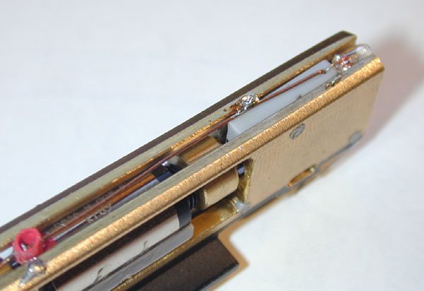 The last step before you run your locomotive is to make a minor change to the wiring.
If you look along the rear end of the chassis, you'll notice a 39-ohm resistor.
This resistor is used to reduce the current to the motor so that it runs at a prototypical scale speed.
The problem is that these little Faulhaber motors aren't terribly strong, and they need all the juice they can get to turn all these gears.
It's not necessary to remove the resistor; you can easily bypass it with a tiny dab of solder (as shown in the photo), which is especially good if you wish to undo this procedure.
It should be soldered to the right side of the chassis (connect it to the wrong side, and it won't run at all).
If, after bypassing the resistor, the locomotive runs too fast for you at full throttle, just turn down the throttle a bit.
The last step before you run your locomotive is to make a minor change to the wiring.
If you look along the rear end of the chassis, you'll notice a 39-ohm resistor.
This resistor is used to reduce the current to the motor so that it runs at a prototypical scale speed.
The problem is that these little Faulhaber motors aren't terribly strong, and they need all the juice they can get to turn all these gears.
It's not necessary to remove the resistor; you can easily bypass it with a tiny dab of solder (as shown in the photo), which is especially good if you wish to undo this procedure.
It should be soldered to the right side of the chassis (connect it to the wrong side, and it won't run at all).
If, after bypassing the resistor, the locomotive runs too fast for you at full throttle, just turn down the throttle a bit.
A good way to troubleshoot is to gently pick up the front half of the chassis with the power still applied, so that the rear truck is still in contact with the rails.
Then try holding the rear.
It should become evident that one truck is picking up power better than the other.
Once you've determined the problematic truck, take it off and try step 7 again.
I've heard that one needs to "break in" these locomotives for several hours for best performance. This may or may not be true, although it should definitely wear down the plastic components a bit, which will make them run more smoothly, especially at the curves. However, if you follow these steps, it should help matters significantly.
Feel free to write me if you have any additions or corrections to this page.
Return Home | Search | Contact Me
Copyright © 2000-2010 D. A. Karp. All rights reserved.